1800 Series Remote Display Retrofit Instructions
- Disconnect all power before servicing.
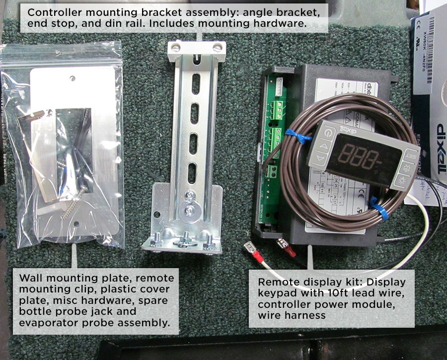
- Inspect the parts kit for the following components
- If the unit is installed, remove the unit.
- Using a #2 phillips screwdriver, remove the front grill and unit top cover.
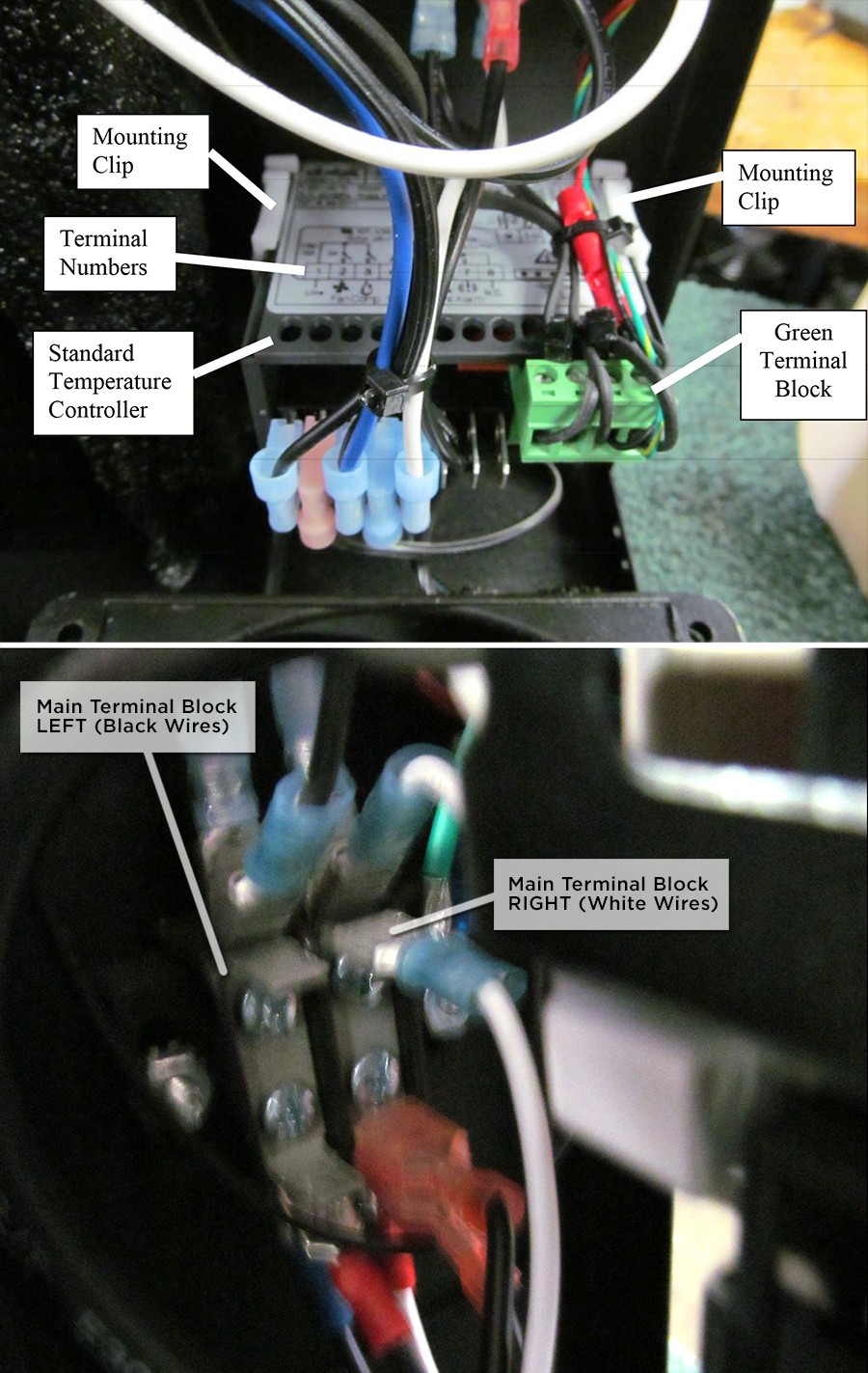
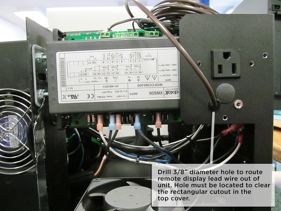
- Locate the standard temperature controller as shown in the photo below. The sticker on top of the controller designates the terminal numbers 1-5. Mark the wires 1-5 and remove all wires from the quick connect terminals. Locate the green probe terminal block, cut the wire ties holding it in place and unplug. Remove the wires marked 1, 4, and 5 from the unit by disconnecting the opposite end from the main terminal block (new wires have been proved on the replacement controller for these connections).
- Once the wires are disconnected from the controller, remove the white mounting clips located on the sides of the controller by sliding a small flat head screwdriver under the release tab and slide the white clip off the rear of the controller. Remove the controller from the front of the unit.
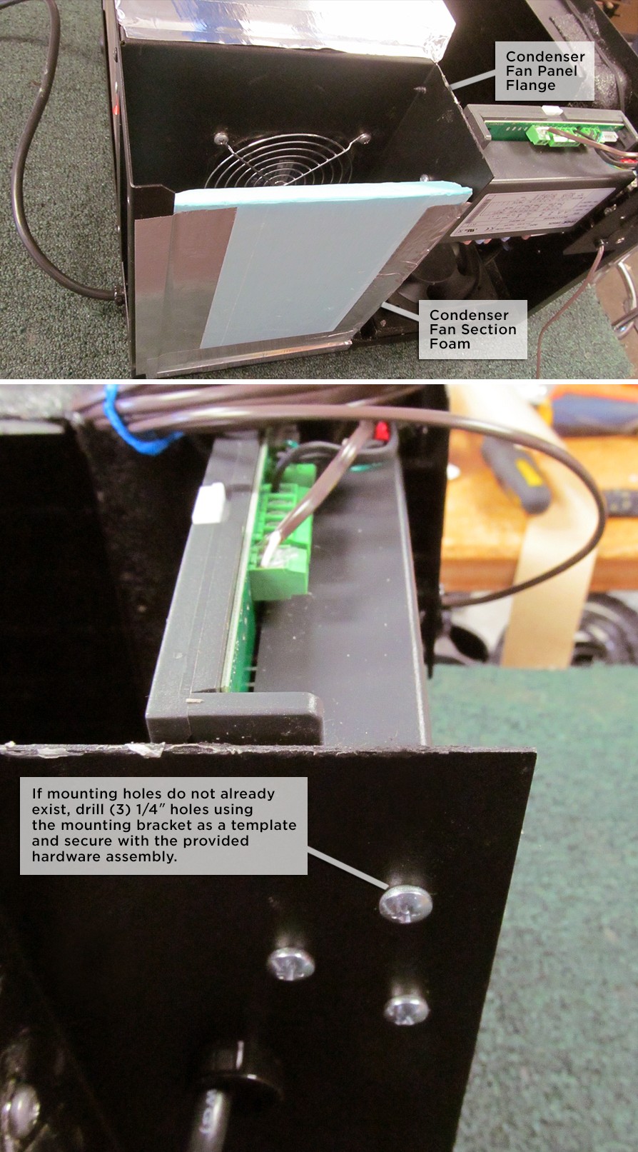
- Locate condenser fan panel. Remove blue foam to access condenser fan panel flange for drilling mounting holes for remote display controller bracket.
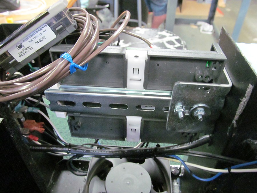
- Locate the controller bracket so that the top of the remote display is even with the top of the bottom chassis, and back far enough so that the controller is fully located inside the unit. Mark (3) mounting holes and drill. Attach with hardware as shown in the photos below.
- Mount the remote display power module to the din rail as shown.
- Connect the wire marked "3" from the standard contoller to terminal "20" on the remote display power module.
- Connect the wire marked "2" from the standard controller to terminal "18" on the remote display power module.
- Connect the opposite end of the black wire connected to the remote display power module terminal "24" to the main terminal block "left" terminal.
- Connect the opposite end of the black wire connected to the remote display power module terminal "25" to the main terminal block "left" terminal.
- Connect the opposite end of the white wire connected to the remote display power module terminal "26" to the main terminal block "right" terminal.
- Probe Connections - remove probe wires from green terminal block. Trace wires and reconnect to the remote power module terminals as indicated below. If the existing wires do not reach, a replacement probe and probe jack are included in the parts kit with longer lead wire, and it will be necessary to replace the bottle probe jack and evaporator probe with this assembly.
- Controller terminal "4" - one lead from condenser probe.
- Controller terminal "2" - one black lead from bottle probe jack, other lead from condenser probe
- Controller terminal "1" - one lead from evaporator probe green lead bottle probe jack
- Drill a 3/8" od hole in the location shown below to run the 2-conductor remote display lead wire out of the unit. Use the provided snap bushing to secure the wire.
- Connect the remote display lead wires to the power module as follows:
- Controller terminal "10" (+) to remote display red wire
- Controller terminal "11" (-) to remote display white
- Use the provided wire ties to secure all loose wiring.
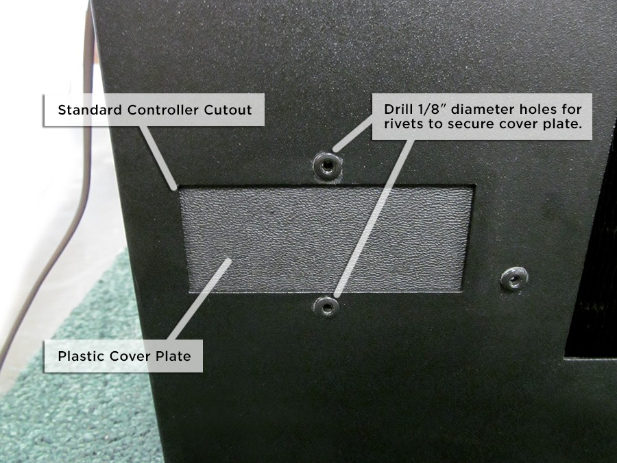
- Drill two 1/8" diameter holes through the unit housing and the plastic cover plate to cover the square hole in the front of the unit where the standard controller was installed, as shown in the picture below. Secure with provided black rivets.
- Using caution, plug in the unit to confirm that the remote display lights up, and after a 3 minute delay the compressor and all fans turn on. Once this is confirmed, turn the unit off. Do not allow the unit to run for an extended period without the top cover. If the unit does not power up, contact the factory for assistance.
- Replace the blue foam in the condenser panel section.
- Remove the remote display from the end of the lead wire, and feed the leadwire though the square hole in the top cover, then place the top cover back onto the unit.
- Replace the front grill.
- Install the unit, and locate and install the remote display with wall mounting plate. On the remote display, connect red to (+) terminal, white to (-) terminal.

We've put together some basic resources to guide you through the process of choosing a cooling unit and building a cellar.


To contact our support team, email us or call 877.726.8496.