VS Series Remote Display Retrofit Instructions
- Disconnect all power before servicing.
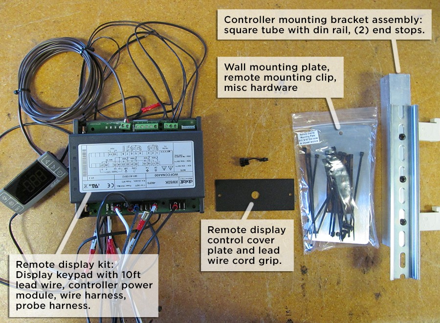
- Inspect the parts kit for the following components:
- Using a #2 phillips screwdriver, remove the front grill and unit top cover.
- Carefully remove the foil tape and blue foam to access the internal components. Make sure all the foam is replaced and all seams taped prior to putting unit back into service.
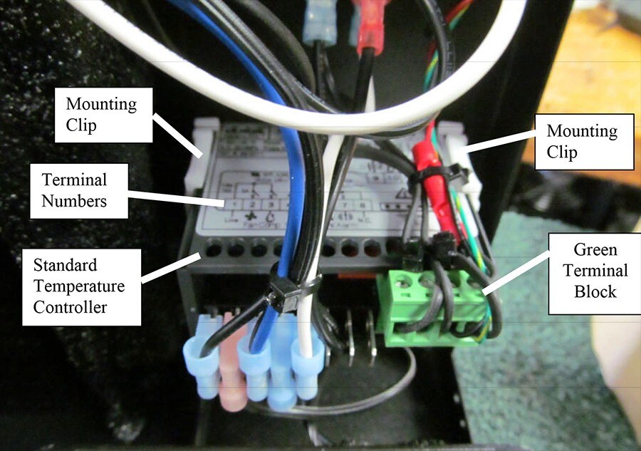
- Locate the standard temperature controller as shown in the photo below. The sticker on top of the controller designates the terminal numbers 1-5. Mark the wires 1-5 and remove all wires from the quick connect terminals. Locate the green probe terminal block and unplug.
- Once the wires are disconnected from the controller, remove the white mounting clips located on the sides of the controller by sliding a small flat head screwdriver under the release tab and slide the white clip off the rear of the controller. Remove the controller from the front of the unit.
- Use the black sheet metal remote control cover plate to cover the opening the controller was removed from. The plate should be mounted from the inside. Hold the plate on the outside to mark the mounting hole locations, drill, then secure plate to the inside using the provided black rivets.
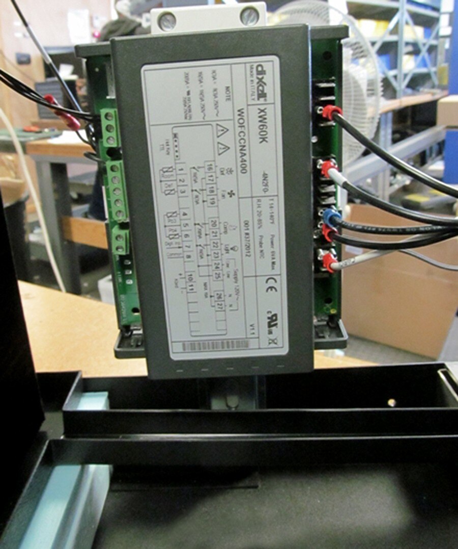
- Install the power module mounting bracket. Drill one 1/8" hole through the internal flange into the square tubing and secure with #8 sheet metal screw (Photo #1). Measure location of center of square tubing from the front of the unit, replace the unit cover, and drill two 1/8" holes through the cover, outer flange, and into the square tubing as shown below. Remove the cover and temporarily secure the square tubing with #8 sheet metal screws (Photo #2). Note that when the retrofit is complete, these two screws are removed then re-installed after the cover is back in place. Once in place, a third screw should be installed by drilling through the cover anchoring into the square tubing near the top of the bracket (Photo #3)
- Install the power module onto the din rail, with end stops positioned top and bottom. Make sure the bottom end stop is above the drain gutter.
- Connect the power module power harness and probe wiring, removing the original wiring as necessary:
- Connect the two wire harness leads marked "T4" to the left side of the front terminal block (black wires).
- Connect the wire harness lead marked "T5" to the right side of the front terminal block (white wire).
- Connect the wire harness lead marked "M4" to the "4" terminal of the fan speed selector switch.
- Connect the wire harness lead marked "14" to the "14" terminal inside the compressor junction box.
- Splice the lead for the condensate heater safety thermostat to one leg of the condensate heater (trace original wiring and cut at red splice).
- Probe Connections - replace the existing bottle probe jack and coil probes with the new assembly. P1 is the room temperature probe located on the face of the evaporator coil, and P3 is the condenser probe located in the fins of the condenser coil.
- Disconnect the remote display head and run the lead wire out through the cover plate hole, securing with the provided cord grip. Reconnect the remote display head lead wires to the power module as follows:
- (+) to remote display red wire
- (-) to remote display white wire
- Use the provided wire ties to secure all loose wiring.
- Using caution, plug in the unit to confirm that the remote display lights up, and after a 3 minute delay the compressor and all fans turn on. Once this is confirmed, turn the unit off. Do not allow the unit to run for an extended period without the top cover. If the unit does not power up, contact the factory for assistance.
- Replace the blue foam, cutting out where necessary to clear the remove mounting bracket. Seal all seams air tight with foil tape.
- Replace the cover, and secure the mounting bracket square tubing with the (3) screws through the cover. Replace the front grill (if provided).


We've put together some basic resources to guide you through the process of choosing a cooling unit and building a cellar.


To contact our support team, email us or call 877.726.8496.